
User’s Manual – StruBIM Design

- Introduction
- Description
- Introduction to a new project
- BIM Model
- Column Design
- Shear Wall Design
- Floor plans
- Drawings
- More information
- Strubim suite. General information
- StruBIM Design. User’s Manual
- StruBIM Design. General reference
- Watch and Learn
- StruBIM Suite (4:41)
- StruBIM Design. 1 NEW PROJECT (2:32)
- StruBIM Design. 2 COLUMN DESIGN (2:18)
- StruBIM Design. 3 WALL DESIGN (2:27)
- StruBIM Design. 4 SLAB DESIGN (2:13)
- StruBIM Design. 5 CONCRETE BEAM DESIGN (2:27)
- StruBIM Design. 6 PUNCHING SHEAR DESIGN (2:04)
- New project from Revit IFC file (5:08)
- StruBIM Design. New Features 2017 b (4:22)
- Features of StruBIM versions
- Strubim suite. General information
Introduction
StruBIM Design is a tool for the automatic design, checking and editing of structural elements of reinforced concrete, steel or composites of both steel and concrete, based on a structural model and a calculated analytical model.
The structural model can be imported by using a file of IFC format, either generated from CYPE IFC Builder or other BIM modeling programs or a file of XML format. The calculated analytical model is imported from StruBIM Analysis or from an XML file, provided that it contains the necessary information.
StruBIM Design carries out the automatic design and checking of the structural elements, columns, beams, slabs and walls, and obtains drawing plans according to the needs of the project (Record Engineer).
The program designs and checks the reinforcements of the following types of reinforced concrete elements, according to ACI 318-14, ACI 318-11 and ACI 318-08 code:
- Columns with rectangular or circular cross-sections
- Beams with rectangular cross-sections
- Solid cross-section slabs
- Solid cross-section walls
The program also designs and checks the following types of columns and beams, according to ANSI/AISC 360-10 code:
- I section
- Hollow rectangular section
- Hollow circular section
- Rectangular box
It checks the following types of composite columns, according to ANSI/AISC 360-10 code:
- Rectangular filled with concrete
- Rectangular box of rolled steel plates, filled with concrete
- Circular filled with concrete
- Reactangular with encased section
- Circular with encased section
The program carries out checks of slab punching shear of slabs on columns without beams. It automatically generates the critical section for each column that transmits stresses to the slab. In this critical section, it verifies the resistance to tangential tension in slabs resisting flexure in both directions.
The results of the automatic design process can be edited and the checking process can be carried out after changes are made, both in reinforced concrete (sections and reinforcements) and in steel sections.
The results of the design can be directly translated into drawing plans of the different elements, columns, beams, slabs and walls, according to the representation needs and project contents (Record Engineer):
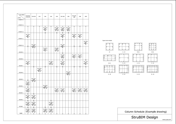
- Column schedule
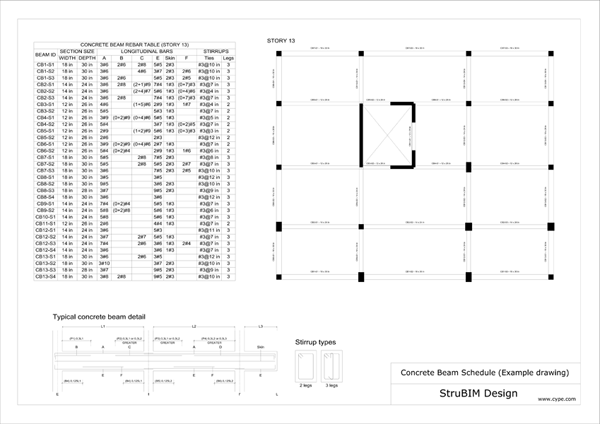
- Beam schedule
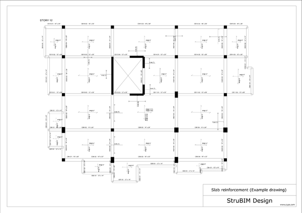
- Drawings of slab reinforcement
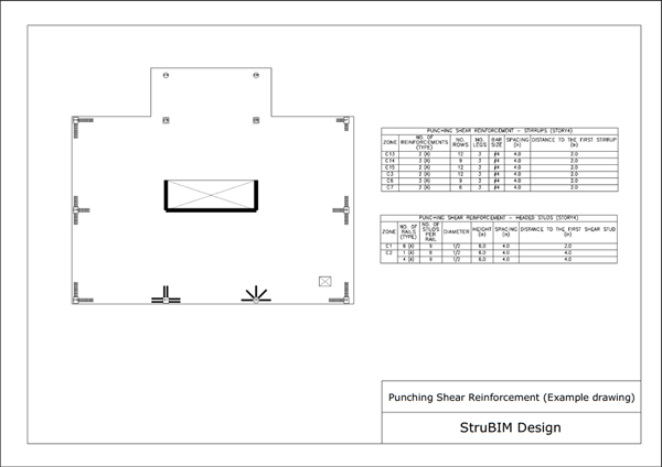
- Table of punching shear reinforcements
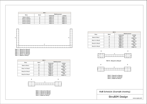
- Wall reinforcement drawings
Example drawings
Description
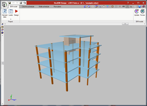
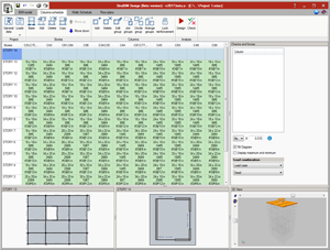
The software consists of general windows that display the model in various views and offer modification options including general data and load details. The upper segment of the main window contains four menus:
BIM model
In this window, the user can obtain a 3D overview of the imported model. The user can also configure the view of the model by its elements, rotation about the axis and projection type.
Column schedule
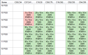
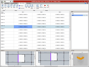
This window allows the user to view the location and details of the columns in every floor. The user can customize and check the column specifications in accordance to the specified regulations. Different types of columns can be checked and dimensioned. The information is organized in a table of columns and floors, referred to as the Column schedule. A summary check list can be generated of the checks that are carried out. The checks are carried out in each point of defined forces. In this list the resulting worst points are shown. The block of columns together with a drawing of the reference sections are presented in drawings, which can also be generated by the user.
Walls schedule
In this window, the user can view the location and details of the walls in every floor. The user can edit, rearrange and further specify wall details through the Elevations menu. The modifications made can be checked to verify if regulations are met. Walls of reinforced concrete can be designed and checked. The information is organized into a table of walls and floors. A summary check list can be generated of the checks that are carried out. The checks are carried out in the transverse section located at the beginning and ending level of each shell that make up the wall. The resulting worst points are shown in this list.
Floor plans
The design of elements contained in the floor plans of the building is conducted in this window, including design of slabs, concrete beams, steel beams and reinforcement for punching shear. The user can edit the reinforcements and properties of slabs, show forces and areas needing reinforcement in slabs. From this window, the beam schedules can also be accessed for concrete and steel beams.
Introduction to a new project
Creating the project
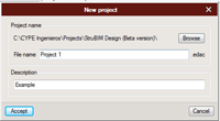
Similar to other software, we begin with the New command from the File menu to introduce the name and description of the new project.
Initial data input assistant
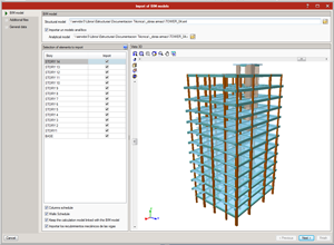
After continuing from the New project window by clicking on Accept, the program will ask the user if it is desired to begin the project by importing a BIM model. If the user chooses to import a BIM model, the following window will appear.
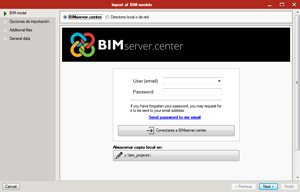
The user can either choose to import a BIM model from BIMserver.center or from a local or shared directory by selecting the desired option from the bar at the top of this window. New project assistant begin to import the project´s data. In this window the user can view the imported model, select the elements to import and adjust the drawing properties and combinations.
From the XML file the following elements and properties are imported:
- Stories and story height
- Beams and columns including:
- I/Wide flange sections
- Round and rectangular concrete and HSS steel columns
- Rectangular concrete beams
- Section dimensions
- Concrete, steel and rebar materials
- Clear and mechanical covers
- Walls and slabs including:
- Thickness and materials
Customize general data
In addition to the imported information, it is necessary to define the required data for the design and verification of the elements. The program determines default values that can be adjusted by the users. This can be done during the import process or at any time afterwards by selecting the General Data option.
 General Data
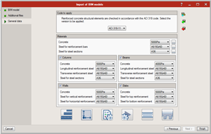
This option will allow users to view the same General data window that was available during the import process at any time during designing. It can be found in the Project section of any window.
In General Data users can modify:
- Design code: Reinforced concrete structural elements are checked in accordance with the ACI 318 code. The user can select the version to be applied:
- ACI 318-14
- ACI 318-11
- ACI 318-08
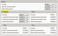
- Materials: materials can be generally defined for the project, although materials can be more specifically defined for each type of element, as well.
 Reinforcement diameter list
Users can specify the reinforcing bar sizes and headed studs available for the design of concrete structures.
-
 Clear covers
Users can modify the clear covers for columns, walls, beams and slabs.
 General design properties
Users can modify strength reduction factors and other properties for concrete and steel design.
-
 Design options
Users can modify rebar rules and preferences for automatic design of columns, walls, beams and slabs.
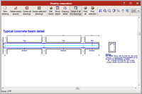
 Typical concrete beam detail
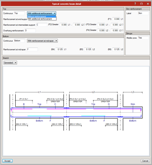
Users can modify a typical detail for the beam design with continuous reinforcement and without additional reinforcement or with continuous and additional reinforcement.
 General options for continuous beams
Users can modify aspects including the angle to generate continuous beams, order for numbering of continuous beams and generation of references for continuous beams.
BIM Model
In this tab, a 3D view of the imported model can be viewed. As well, the general options for the project can be accessed by the user.
The user can adjust the display options for columns, walls, beams, slabs and axes, as well as the graphic options and length representation.
- General data
 Loads
Loads
The Loads drop-down menu shows several options for displaying loading. These include Load patterns, Load cases, Combination groups and Limit states.
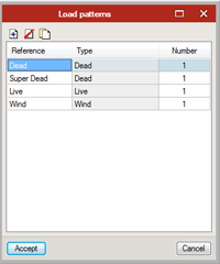
 Load patterns
The user can add new load patterns or edit the existing ones by selecting this option. A reference will need to be input for the load pattern and then a type can be specified. For the type, the user may choose between Dead, Super Dead, Live, Reducible Live, Roof Live, Notional, Seismic, Seismic (Drift), Wind, Snow, Construction and Other.
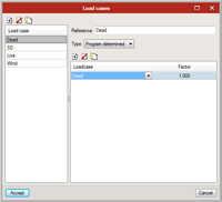
 Load cases
The user can create or modify specific load cases including different proportions of existing load patterns, as previously defined. A reference will again need to be input for the load case and then specific load patterns can be applied to each case, with the factor for its proportional influence. The type for the load case can either be determined by the program or specified by the user.
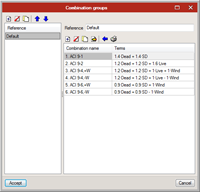
 Combination groups
Combination groups can be added or modified. A combination name will need to be specified and then existing load cases or other combinations can be added to each combination group in proportions which are specified by a user-inputted factor.
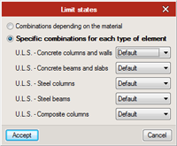
 Limit states
Limit states can be specified for combinations, either depending on the material or the type of element.
 Design
The software can run the automatic design analysis by using the Design tool, which will design in accordance with the selected requirements.
 Update
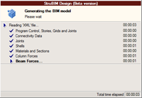
Selecting this option will re-generate the BIM model, running the New project assistant again, as seen when the file was originally imported.
 Forces
Allows the user to import new forces to the current BIM model.
Column Design
General
The software’s Columns schedule enables the design of columns from an imported model. By selecting a cell, the user can view the location of each column in the lower and upper stories and in 3D view.
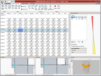
To the right of the window, under Checks and forces, the user can consult the forces of each column by load case or by load combination and its buckling properties.
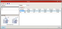
Under Checks and forces, by selecting the first option next to the column selection the user can access the Forces window where forces can be inputted and load cases defined.
![]()
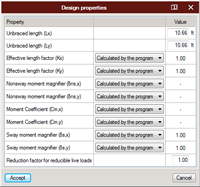
By selecting the “gear” symbol next to the column selection the user can access the Design Properties window. Properties can either be calculated by the program or user defined.
![]()
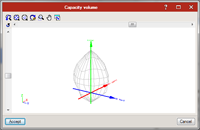
By selecting the third option next to the column selection the user can access the Capacity volume window.
![]()
The green arrow ![]() and red
and red ![]() to the far right of the column section will be discussed later in this section.
to the far right of the column section will be discussed later in this section.
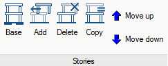
Stories menu
Stories can be edited within the Column Schedule window with the options seen in the Stories section:
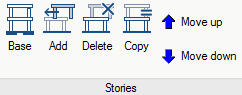
 Base
Base
Selecting Base will allow the user to define a reference for the base.
 Add
Add
Selecting Add will display a window where the user may define a reference and add a new story. As well, in this window the user may overwrite design properties pertaining to concrete columns, steel columns and composite columns.
 Delete
Selecting Delete will allow the user to delete the stories within the column schedule. Select the story that is desired to be deleted and then select the Delete option.
 Copy
Copy
Selecting Copy will allow the user to make a copy of the selected story. Select t he story that is desired to be copied and then select Copy.
 Move up, Move down
Selecting Move up or Move down will allow the user to move the selected story up or down within the structural model.
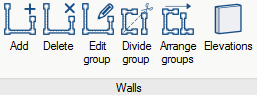
Columns menu
Columns can also be edited within the Columns Schedule window with the options seen in the Columns section:
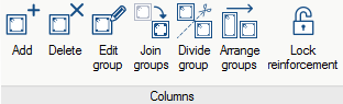
 Add
Add
Selecting Add will allow the user to add columns. The user will have the option of assigning the new column(s) to an existing column group. A reference for the new column(s) must be created.
 Delete
Selecting Delete will allow the user to delete existing columns. A window will appear with a drop-down menu including all column groups. When a column group is selected, the individual columns within the group will appear. The user may then select which columns will be deleted.
 Edit group
Selecting Edit group will allow the user to edit a group of columns by moving individual columns up or down within the group.
 Join groups
Selecting Join groups will allow the user to select a Master column group and then select other column groups to add to the master group, therefore joining the groups.
 Divide groups
Selecting Divide groups will allow the user to create a new column group by selecting a group to divide and then selecting which columns will be divided into the new column group.
 Arrange groups
Selecting Arrange groups will allow the user to arrange column groups by moving them up or down.
 Lock reinforcement
Selecting Lock reinforcement will allow the user to keep the reinforcement of a particular column or column group during the design process. This option can be useful when a specific reinforcement needs to be input and others designed.
 Display visible columns
Allows the user to specify which column groups will be visible in the column schedule.
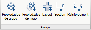
Assign menu
Design properties and other details can be assigned for specific columns or column groups using the following options in the Assign menu:
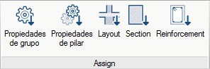
 Group design properties
Allows the user to select and modify specific column groups and stories within the Column schedule. The user can override the automatic values for these groups.
 Column design properties
Allows the user to select and modify other values for the design of the reinforcement for specific columns, rather than entire columns groups.
 Layout
The user can select specific column groups and select which layout is desired for each, choosing between the following options: “Passes through the floor,” “Does not pass through the floor,” and “Exempt”.
 Section
Allows the user to select specific columns groups and modify the cross section of each column, as well as the X/Y dimensions of each column. Users can choose between materials including concrete, steel, and composite, and then choose the specific cross section style from the available options for each material.
 Reinforcement
After selecting the specific column groups desired, the user can modify reinforcement in each column groups. The user can modify the longitudinal reinforcement, transverse reinforcement, and whether all bars are tied or every other bar is tied for the X/Y faces.
Cell
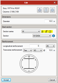
By double-clicking on a cell, the user can view or edit the basic information about the column including orientation with the floor, material and cross section type, design properties, dimensions and reinforcement.
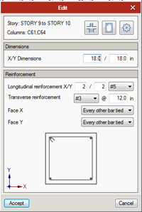
The user can edit the following information using the three buttons found near the top of the Edit window, next to the selected story and columns:
 With this option, the user has the choice of determining the columns orientation with the floor: Passes through the floor, Does not pass through the floor or is Exempt, based on the following selections:
 Passes through the floor
 Does not pass through the floor
 Is Exempt
 Section
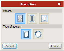
With this option, the user can determine the material (concrete, steel or composite) and the type of section, depending on the material selected:
 Design overwrites
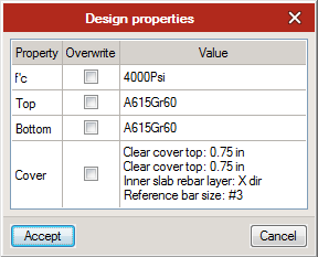
With this option, the user can overwrite the input properties that are determined based on the standards applied in General Data. The overwrites that could potentially be made are seen in the following table by selecting this option:
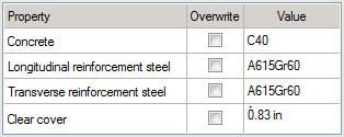
To overwrite a value, simply check the box in the Overwrite column and input the values that are desired in the Value column.
For steel and composite columns, the steel sections can be imported, created or modified by the user. In the Edit window, under Steel section, the user can select either New, Edit the selected type or Edit the list of elements. These options appear next to the Section series for the steel section.
The New option will allow the user to add a new section series, in addition to those which are already available. Edit the selected type will allow the user to modify the section series which is currently selected. Edit the list of elements will display all currently available section series, which can then be modified by adding a new series, editing a current series or choosing from other options such as importing new elements from a predefined section series or creating new elements based on a file.
Selecting to add or edit a series under any of these options will prompt the user to create or modify a reference and description for a series. Once this has been done and the user has chosen to either add or modify a series, a window will appear with various options for user input.
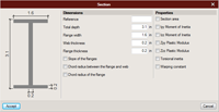
This is how the user can determine the specifications of the steel section for either a steel or composite column.
Analysis menu
 Check
Check
With the Check option, the user can check whether or not inputted values are in accordance with the specified requirements. This can be used to check values that the user inputs for columns.
- Design
With the Design option, the program automatically designs the features to meet the specified requirements.
Check
Once the program finishes the design process, green cells will appear if all criteria meet required ACI 318 regulations.
If all regulations are not met, the cells will appear red. A summary can be accessed detailing the problem(s) that occurred.
The user can access a summary with the results from all the checks performed by double-clicking icon ![]() (if regulations are met) or icon
(if regulations are met) or icon ![]() (if regulations are not met) that is seen next to the specific column under the Checks and forces section on the right-hand side.
(if regulations are not met) that is seen next to the specific column under the Checks and forces section on the right-hand side.
![]()
![]()
After double-clicking icon ![]() or icon
or icon ![]() , a summary similar to the following will appear, with all invalid checks highlighted red:
, a summary similar to the following will appear, with all invalid checks highlighted red:
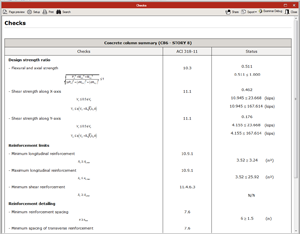
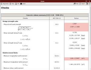
The summary can then be exported in PDF, DOCX, text, HTML or RTF format by selecting the Export option in the top ribbon.
![]()
A report can be accessed of all information of the current project, including descriptions, forces, reinforcements, design properties and checks of columns, walls, slabs and beams.
![]() Select Reports (highlighted) and the following window will appear:
Select Reports (highlighted) and the following window will appear:
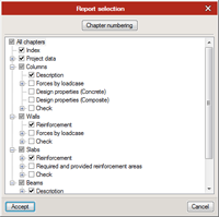
In this window, the user has the option to choose exactly which items are desired to appear in the reports of the project. After making the selection and clicking accept, the following window will appear with the reports:
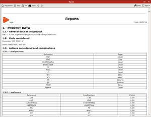
The reports can be printed, shared or exported by using the options in the top ribbon of the window.
The user can also view and export the column table through Drawings on the upper ribbon, selecting Add new element to the list and then Column Schedule from the Drawing Type menu.
Shear Wall Design
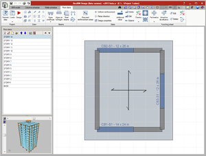
General
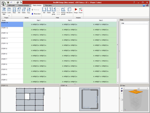
In the Wall schedule tab, the user can click a cell to view the selected wall´s location in the lower and upper stories and in 3D view.
Stories menu
Stories can be edited within the Walls schedule window with the options seen in the Stories section:
 Base
Base
Selecting Base will allow the user to define a reference for the base.
 Add
Add
Selecting Add will allow the user to add a new story to the Walls schedule. A reference will need to be created and a height will need to be inputted for the new story. The user may overwrite design properties for the new story.
 Delete
Selecting Delete will allow the user to delete stories within the walls schedule. The user should select the story that is desired to delete and then select the Delete option.
 Copy
Copy
Selecting Copy will allow the user to make a copy of the selected story. Select the story that is desired to be copied and then select Copy.
 Move up, Move down
Selecting Move up or Move down will allow the user to move the selected story up or down within the structural model.
Walls menu
Walls can also be edited within the Walls Schedule window with the options seen in the Walls section:
 Add
Add
Selecting Add will allow the user to add walls. The user will have the option of assigning the new wall(s) to an existing wall group. A reference for the new wall(s) must be created.
 Delete
Selecting Delete will allow the user to delete existing walls. A window will appear with a drop-down menu including all wall groups. When a wall group is selected, the individual walls within the group will appear and the user may then select which walls will be deleted.
 Edit group
Selecting Edit group will allow the user to edit a group of walls by moving individual walls up or down within the group.
 Divide groups
Selecting Divide groups will allow the user to create a new column group by selecting a group to divide and then selecting which columns will be divided into the new column group.
-
 Arrange groups
Selecting Arrange groups will allow the user to arrange wall groups by moving them up or down.
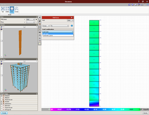
 Elevations
Selecting Elevations will allow the user to see the forces and the tensions of each wall by load case or by combination group. Forces will be shown in a color-coded model based on user preferences:
 Display visible walls
Allows the user to specify which walls will be visible in the Wall schedule.
Assign menu
Similar to the Assign menu of the Columns schedule, design properties and other details can be assigned for specific columns or column groups using the following options:
 Group design properties
Allows the user to select and modify specific walls and stories within the Wall schedule. The user can override the automatic values for these walls.
 Wall design properties
Allows the user to select and modify other values for the design of the wall reinforcement, including resistance to buckling and reinforcement limits.
-
 Layout
The user can select specific walls and select which layout is desired for each, choosing between the following options: “Passes through the floor,” “Does not pass through the floor,” and “Exempt”.
 Section
Allows the user to select specific walls and modify the cross section of each, including the details of the wall section itself, details of the reinforcement strips, and the dimensioning of the walls:
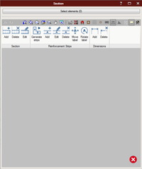
 Reinforcement
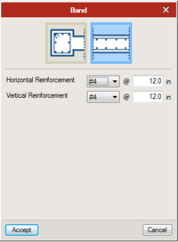
After selecting the specific walls desired, the user can modify reinforcement. The user can modify the horizontal or vertical reinforcement bands, as well as their orientation.
Cell
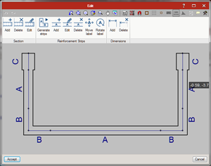
By double-clicking on a cell the user can access the Edit window, where the user may view the wall sections and the reinforcement strips.
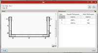
Reinforcements can be locked by clicking on the tiny “lock” symbol in the upper right hand corner of the Edit window, as highlighted below:
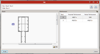
Reinforcement bands can be edited by double clicking on either the horizontal or vertical reinforced that is desired to edit, which will produce the Band window:
 Reinforcements and sections can be added or edited by selecting the Edit button at the bottom of the Sketch section of the Edit window.
Reinforcement strips can either be added by the user or generated by the program. The user can either select Generate strips or Add from the Reinforcement Strips section of the upper ribbon.

 Show
Show
Selecting Show will allow the user to see the floor below the current floor, shown with pink lines.
 Copy
Copy
Selecting Copy will allow the user to copy the floor below to the current selection.
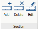
 Add
Add
Selecting Add will allow the user to first define a wall section thickness and then draw a new wall section. Right click to select a beginning vertex and then select the ending vertex.
 Delete
Selecting Delete will allow the user to eliminate wall section. Select the Delete option, right click on the wall that is desired to be deleted to select it and then left click to delete it.
 Edit
Edit
Selecting Edit will allow the user to change the thickness of a wall. Select the Edit option and then left click on the wall that is desired to be changed.
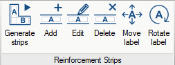
 Generate strips
Selecting Generate strips will automatically introduce reinforcement, deleting any previously introduced reinforcement.
 Add
Add
Selecting Add will allow the user to introduce reinforcement strips, after defining a label. Right click to select a beginning vertex for the reinforcement strip and then select the ending vertex.
 Edit
Edit
Selecting Edit will allow the user to change the label of the selected reinforcement strips. Select Edit and then select the reinforcement strips desired to edit to change the label(s).
 Delete
Selecting Delete will allow the user to eliminate reinforcement strips. Select the Delete option, right click on the reinforcement strip that is desired to be deleted to select it and then left click delete it.
 Move label
Selecting Move label will allow the user to move the label of any reinforcement strip. Select the Move label option, select the label that is desired to be moved and then select a new location to place the label.
 Rotate label
Selecting Rotate label will allow the user to rotate the label of any reinforcement strip. Select the Rotate label option, select the label that is desired to be rotated and then select the new orientation of the label.

 Add
Add
Selecting Add will allow the user to add dimensions to any wall section or reinforcement strip. Select the Add option, select a beginning point for the dimension line and then select an ending point.
 Delete
Selecting Delete will allow the user to eliminate dimension lines. Select the Delete option, right click on the dimension line that is desired to be deleted and then left click to delete it.
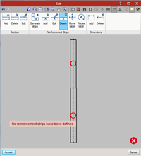
Error messages will appear as a red circle in the affected section of the wall and a red circle with a centered “x” will appear in the bottom right corner of the window. Hovering over the red circle will display the error message for the user to read. Clicking Accept will finalize the changes that were made.
Analysis
As with the columns of the Column schedule, walls can be automatically designed or checked using the Analysis menu.
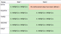
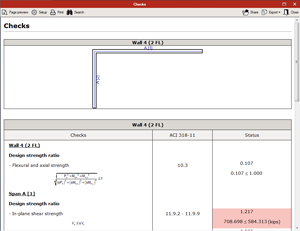
After designing or checking, green cells will appear if all criteria meet required ACI 318 regulations.
If any walls do not meet the specified requirements, the corresponding cells will appear red and contain an error message.
The user can access a summary with the results from all the checks performed by double-clicking icon ![]() (if regulations are met) or icon
(if regulations are met) or icon ![]() (if regulations are not met) that is seen next to the specific column under the Checks and forces section on the right-hand side. Again, any issues will be highlighted red:
(if regulations are not met) that is seen next to the specific column under the Checks and forces section on the right-hand side. Again, any issues will be highlighted red:
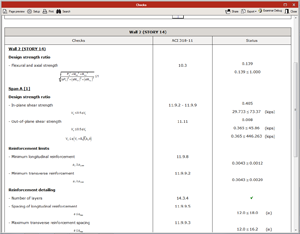
The summary can then be exported in PDF, DOCX, text, HTML or RTF format by selecting the Export option in the top ribbon.
![]()
The user can view the summary with the results from all the checks performed and export it through Drawings>>Add new element to the list>>Walls schedule.
Floor plans
General
This window is for the design of elements in each level of the floor plans: concrete beams, steel beams, reinforcement concrete slabs and punching shear reinforcements.
Project menu
![]() Copy to other plan: This option allows the user to copy different defined properites of the current plans to other plants. The following can be copied:
Copy to other plan: This option allows the user to copy different defined properites of the current plans to other plants. The following can be copied:
- Beams
- Section
- Reinforcement. Reinforcements will be copied when the beams are part of similar arrangements
- Slabs
- Section
- Rebar direction
- Aditional reinforcement
- Critical section and punching shear reinforcement
Draw menu
Within the Draw menu of the Floor plans window, there are many options available to the user for editing:
 Grid lines
This option allows the user to draw grid lines, after defining a reference.
 Walls
Walls
This option allows the user to create new walls, after defining a reference. The user also inputs a thickness for the wall and decides whether or not it is a base or head wall. Select a beginning vertex for the wall and then select an ending vertex to place the wall.
 Columns
This option allows the user to create new columns, after defining a reference. The user also chooses the shape of the cross-section, inputs values for x/y dimensions and decides whether or not it is a base or head column. Simply left click on the desired location to place the column.
 Slabs
Slabs
This option allows the user to create new slabs, after defining a reference. Right click the points that are desired as vertices for the slab and then left click to place the slab once all points have been selected.
 Beams
Beams
This option allows the user to create new beams, after defining a reference. The user also chooses the material, inputs dimensions and determines whether initial and final nodes are supported or overhang. Select a beginning vertex for the beam and then select an ending vertex to place the beam.
 Openings
This option allows the user to create an opening in a slab, after defining a reference. Right click the points that are desired as vertices for the slab and then left click to create the opening once all points have been selected.
 Edit
Edit
This option allows the user to select and edit features by checking the corresponding boxes Delete: This option allows the user to select and delete features by checking the corresponding boxes. Left click to select the object and right click to delete it.
 Move a group of elements
This option allows the user to select which types of objects need to be moved from a list of check boxes. Select them by left clicking, right click to move them to a new location and then left click again to place them.
 Copy
Copy
This option allows the user to select and copy longitudinal and/or transverse reinforcement.
 Symmetry (Copy)
This option allows the user to copy objects and paste them in a location determined by rotating around a fixed point. Left click to select objects to copy and right click to rotate and place them.
 Rotate a group of elements
This option allows the user to move objects by rotating them around a fixed point. Left click to select objects and right click to move and place them.
 Move
Move
Allows users to create a copy of an element in a new location. Select the Move option, select the object that is desired to be copied and select the new location for the copy.
 Symmetry (move)
This option allows the user to move objects by rotating them around a fixed point. Left click to select objects and right click to rotate and move them.
 Display options
With Display options, the user can edit preferences about the display of columns, beams, walls, slabs and punching shear, as well as graphics options and length representation.
Beam Design
Concrete or Steel beam design can be conducted in the Floor plans tab under the Beams section.
In the Floor plans tab, the user can consult imported forces and view and edit details in General data>> Typical concrete beam detail. Other details can be edited in General data including specifications for concrete, longitudinal reinforcement steel, transverse reinforcement steel and steel for steel sections.
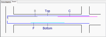
In this window, continuous reinforcements alone or with additional reinforcements can be defined and the reinforcement labels and longitudes can be edited.
- Design
Once the properties have been defined, the program can run the automatic beam design.
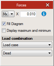
 Display forces
Forces in the beams can be consulted by load case or combination group and can be consulted for both dead loads and live loads. The following window will appear:
 Beam forces
After selecting this option, the user can select a specific beam in the plan, which will produce the following window:
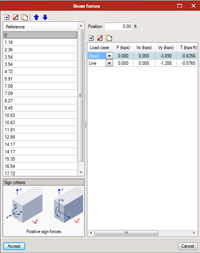
It should be noted that when beams are created within the floor plane, forces will need to be introduced to the beam(s) using this option.
Concrete Beam Design
![]() Concrete beams can be designed in the Concrete beam schedule. In this window, the user can view the beams in each floor with their respective dimensions, design properties and reinforcements.
Concrete beams can be designed in the Concrete beam schedule. In this window, the user can view the beams in each floor with their respective dimensions, design properties and reinforcements.
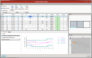
On the lower section of the screen we can see the forces, the required areas and the detail type.
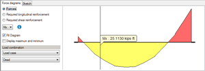
The user can edit the software´s proposed reinforcements and analyze the beam.
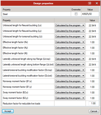
Double-clicking the button with a graphic of a gear will allow the user to access the Design properties window. In this window, the user can choose to overwrite values for various properties or select predetermined values from the program.
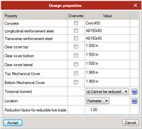
Users can select the “gear” symbol next to the beam selection in order to access the Design properties window.
![]()
In this window, the user has the option to overwrite predetermined values for properties of the beams, determine whether torsional moments can or cannot be reduced by redistribution of internal forces, determine location for structural integrity requirements and define the reduction factor for reducible live loads.
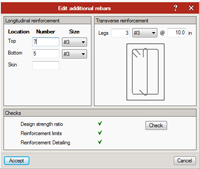
Users can select the four reinforcement sections, Top, Bottom, Skin and Stirrups in order to access the Edit additional rebars window.
![]()
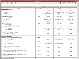
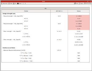
In this window, users have the option of inputting data pertaining to Longitudinal reinforcement and Transverse reinforcement, as well as conducting checks on the additional rebars for Design strength ratio, Reinforcement limits and Reinforcement Detailing.
As well, to the far left of the row for each column, the user has the option to lock the reinforcement of each beam, similar to locking the reinforcement of columns or walls.
Also as with columns and walls, a summary can be generated for beams. The summary shows the results and the areas where reinforcement is needed and is once again accessed by double-clicking icon ![]() or
or ![]() that appears in the row of the beam.
that appears in the row of the beam.
The summary can be exported by clicking on Drawing>> New drawing>> Floor plans. In this drawing the beam table and detail type of each floor are shown. This drawing can also be exported as a CAD file.
Steel Beam Design
![]() Steel beams can be designed in the Steel beam schedule. In this window, the user can view the beams in each floor with their respective dimensions, design properties and reinforcements, much like the process for concrete beams.
Steel beams can be designed in the Steel beam schedule. In this window, the user can view the beams in each floor with their respective dimensions, design properties and reinforcements, much like the process for concrete beams.
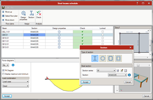
As with the concrete beam schedule, on the lower section of the screen we can see the forces and required areas.
Double clicking on the “gear” symbol under the Design properties column will open a window of the same name. Similar to the options available for concrete column properties, users have the option to overwrite several properties, as can be seen in the following window:
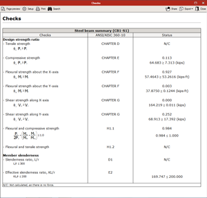
A summary can be generated for the steel beams. The summary shows the results and the areas where reinforcement is needed and is once again accessed by double-clicking the green arrow or red x that appears in the row of the beam in the Steel beam schedule after designing.
Concrete Slab Design
General
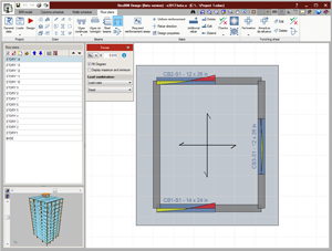
In the Floor plans tab, the imported forces can be consulted by load combination or by load case.
Slabs menu
With the slabs menu, there are many options available to the user for the design and checking of slab reinforcement.
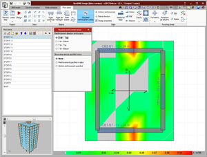
 Display forces
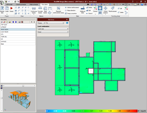
With this option, the user can display the forces on the slab with a color scale. This can be done through load case or combination group and can be done for live loads or dead loads.
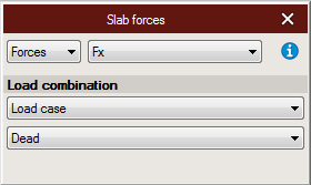
 Slab forces
With this option, the user can input forces on the slabs by either vertex or tessera and can also define the load case. Select Slab forces and then select the slab that is desired.
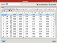
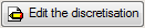
By selecting Edit the discretisation, the user can edit the thickness, vertices, tesseras and vertex indexes.
 Required reinforcement areas
The user can view the calculated required reinforced areas. With this tool, we can reduce a certain amount of reinforcement to the necessary areas.
 Checks
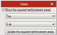
Once the reinforcements have been defined, the program can run a check on the beams. For slabs, the user chooses whether to consult, update or show/hide the checks. Checks for resistance and reinforcement limits will be performed in accordance to ACI 318 regulations.
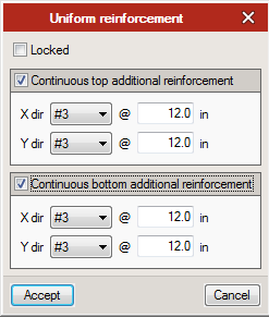
 Additional rebar
In addition to continuous reinforcement, we can add additional reinforcements on top as well as on the bottom, in any direction and update the necessary areas.
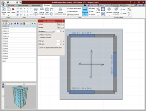
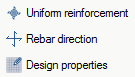 Uniform reinforcement, rebar direction, design properties
There are several other options that the user can select for the design of the slab and its reinforcement:
- Uniform reinforcement: The user can define uniform reinforcement by selecting this option, left-clicking on the desired slab to highlight it and then right-clicking to display the Uniform reinforcement window. Both additional continuous top and bottom reinforcement can be selected and defined.
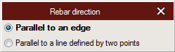
- Rebar direction: Selecting this option will display the Rebar direction window. Direction can be selected to be parallel to an edge or parallel to a line defined by two selected points.
- Design properties: The user can view and/or overwrite the design properties by selecting this option, which will cause the Design properties window to appear.
 Delete, Edit, Extend
With these options, the user can choose to delete additional rebar, edit additional rebar or extend/shorten the rebar.
Finally, we can view and export drawings by clicking Drawings>> New drawing>> Floor plans. In this drawing, we can see slab reinforcements.
Punching shear design
General
In the Floor plans tab, it is possible to design for punching shear reinforcement.
Punching shear menu
In this menu, the user can design for punching shear in slabs within the floor plans.
 Critical sections
Critical sections can be generated in slabs with the options available in the Punching shear section of the Floor plans tab. With this option, users can Add, Edit, Delete, or Generate critical sections.
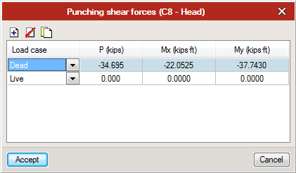
 Forces
Selecting this option will cause the Punching shear forces window to appear. These forces can be displayed for any specific column head or base that is applicable:
 Consult checks
Selecting Generate allows the user to see potential affected areas, and then check these areas to see if they comply with specified design code requirements. Check can continue to be used as the areas are edited or added by the user.
-
 Reinforcement
When sections susceptible to punching shear reinforcement are found, additional reinforcement can be added by selecting this option. Reinforcement causes the Draw additional rebar window to appear.
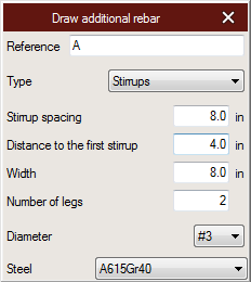
In this window, the user can choose between reinforcement of stirrups or studs. Additional information is then inputted about the details of the reinforcement, before it is drawn by the user. Once all details have been finalized, the user can draw reinforcement in the necessary areas, and once again select the Check option to ensure that the section now complies with design code regulations.
 Additionally, the added reinforcement can be edited or deleted. Selecting Edit will once again cause the Draw additional rebar window to appear, while selecting Delete will give the user the option to eliminate the added reinforcement.
Drawings
Creating a drawing
Drawings can be created from any window. In the top ribbon, next to the Save, Undo, Redo, Reports the Drawings option can be found.
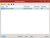
![]() Select Drawings (highlighted) and the following window will appear:
Select Drawings (highlighted) and the following window will appear:
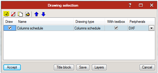
In this window, select Add new element to the list ![]() , which will prompt the Drawing Editor menu or select Edit selected element
, which will prompt the Drawing Editor menu or select Edit selected element ![]() to edit an existing feature of the drawing. The following window will appear:
to edit an existing feature of the drawing. The following window will appear:
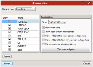
Select the desired Drawing type from the Drawing type drop-down menu and either click Accept or edit the configuration of the drawing, including different options depending on the drawing type, as seen above.
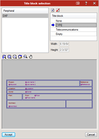
![]() By selecting Title block from the Drawing selection window, the Title block selection window appears, allowing the user to add and edit a title block for the drawing. Either a previously introduced title block can be chosen and edited or a new one can be uploaded. The user has the option of selecting the height and width of the title block.
By selecting Title block from the Drawing selection window, the Title block selection window appears, allowing the user to add and edit a title block for the drawing. Either a previously introduced title block can be chosen and edited or a new one can be uploaded. The user has the option of selecting the height and width of the title block.
![]() By selecting Layers, visible at the bottom of the Drawing selection window, the layers of the drawing can be defined and edited.
By selecting Layers, visible at the bottom of the Drawing selection window, the layers of the drawing can be defined and edited.
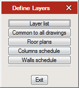
Selecting Layer list allows the user to access a detailed list of all layers that are available to show in the drawings.
Selecting Common to all drawings displays the Layer definition window. This same window can also be displayed for the Floor plans, Columns schedule or Walls schedule by selecting their respective buttons in the Define Layers window.
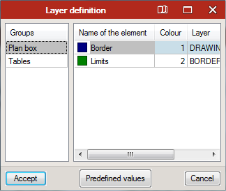
Common to all drawings allows all layers to be edited, with the changes applied to all drawings. If it is desired to define individual drawings, the user should select Floor plans, Columns schedule or Walls schedule, depending on which layer is desired to be edited.
Back in the Drawing selection window, the user may also decide the peripherals for the drawing.
Editing, printing and exporting the drawing
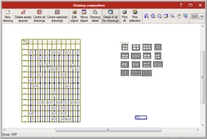
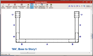
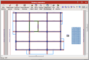
Once all options have been properly selected, the user can select Accept to generate the drawing, which will open the Drawing composition window.

From the Drawing composition window, the user can now view the drawing and its components. The top ribbon displays multiple options for the drawing. New drawing will allow the user to create a new, blank drawing within this window. Delete empty spaces will eliminate any spaces void of objects from the files. Centre all drawings will restore the original position of all components in the drawing. Centre selected drawings will perform the same function, though only for drawings that have been selected.
Edit object will allow a user to move the text objects within the drawing. Move object allows objects within a drawing to be moved either within the drawing or to a different drawing. When moving an object from one drawing to another, objects linked to the selected object will also be moved. Drawing detail will allow the user to view the real layout of an object by clicking on it. This can be undone by clicking once more. Detail of all the drawings will display the real layout of all drawings, rather than just those which are selected.
Print all will print or export all drawings to a desired location. Print selection performs the same actions, though only for selected components.
More information
- Strubim suite. General information
- StruBIM Design. User’s Manual
- StruBIM Design. General reference
- Watch and Learn
- StruBIM Suite (4:41)
- StruBIM Design. 1 NEW PROJECT (2:32)
- StruBIM Design. 2 COLUMN DESIGN (2:18)
- StruBIM Design. 3 WALL DESIGN (2:27)
- StruBIM Design. 4 SLAB DESIGN (2:13)
- StruBIM Design. 5 CONCRETE BEAM DESIGN (2:27)
- StruBIM Design. 6 PUNCHING SHEAR DESIGN (2:04)
- New project from Revit IFC file (5:08)
- StruBIM Design. New Features 2017 b (4:22)
- Features of StruBIM versions
Tel. USA (+1) 202 569 8902 // UK (+44) 20 3608 1448 // Spain (+34) 965 922 550 - Fax (+34) 965 124 950